Anwendung der Filterinduktivität bei der Entstörung von Stromversorgungen
2023-05-18
Kategorie: Unternehmensnachrichten

Application of filter inductor in power supply anti-interference
1 Introduction
With the popularization and development of digital circuits of switching power supplies, the electromagnetic waves radiated and leaked by electronic equipment not only seriously interfere with the normal operation of other electronic equipment, resulting in equipment dysfunction, transmission errors, control failures, but also threaten human health and safety, and have become an invisible pollution, not inferior to the harm of tangible pollution such as water, air, and noise. Therefore, reducing electromagnetic interference (EMI) in electronic devices has become a concern of the world electronics industry. To this end, the relevant decree of the relevant EMC Commission of the European Community came into force on January 1992, 1, which lasted 1 It finally entered into force on 4 January 1996. The decree points out that all products that do not meet the provisions of European and international EMC standards are not allowed to enter the market for sale, and the violation is severely punished, while taking EMC certification and electrical safety certification as the primary conditions for some product certification. This move caused a huge shock in the world electronics market, and EMC became an important indicator affecting international trade. In order to be in line with international standards, China has also successively formulated relevant EMC regulations. To this end, China has held electromagnetic compatibility standards and demonstration meetings many times, and it is recommended that electronic equipment circulating on the market since January 1, 1 must formulate and design suppression measures against radio interference, and place suppression components. So that the electromagnetic interference generated does not exceed the level specified in the standard. From January 1997, 1, all products entering the market must have the EMC mark. This is the first step for China's electronic products to participate in the international market competition.
2 Anti-interference filter characteristics
There are conceptual differences between anti-interference filters and conventional signal filters. The signal filter works under the condition of impedance matching, that is, through the filter to keep the amplitude of the input and output signals unchanged, part of the frequency domain is processed and transformed as expected. The EMI filter is used to suppress electromagnetic interference entering and exiting the device, and has bidirectional suppression. Therefore, this requires maximum mismatch between the port of the EMI filter and the device. In this way, the attenuation of electromagnetic interference by the filter is equal to the attenuation of its own network plus the reflection generated by the input and output ports, and the following rules must be followed, as shown in Table 1. where Rs is the input impedance of the power grid, which changes with the amount of electricity; RL is the output impedance of the EMI filter and varies with the size of the load.

From an electrical point of view, maximum absorption (or loss) can only be generated in the filter under the condition of impedance mismatch, which is called "filter insertion loss" in the EMC parlance ”。 EMI filters are primarily designed to eliminate or reduce conducted interference. In fact, conducted interference is divided into common-mode interference and differential-mode interference, the so-called common-mode interference means that the phase of the interference signal between the phase line and the ground line is the same phase and the potential is equal, and the differential mode interference is the phase difference of 180° (equal potential) of the interference signal between the phase lines. See Figure 1.

Therefore, the filter circuit is also divided into anti-common-mode and anti-differential mode interference circuit, in the figure LC1LC2, Cy1Cy2 constitute a common-mode filter circuit, LC1LC2 is a common-mode filter inductor, and Ld1Ld2Cx1Cx2 forms a differential-mode circuit. The general value of common-mode inductor Lc is 0.3mH~38mH, and the common-mode capacitor Cy, as long as the leakage current is controlled in Under the condition of < 1mA, the larger value is selected. The differential mode inductor Ld is generally tens to hundreds of microhenries, and its capacitance should be selected ceramic or polyester capacitors with a withstand voltage greater than 1.4kV. The larger the Ld1Ld2 differential mode inductance and capacitance value, the better the low-frequency effect. Most of the EMI filters purchased on the market are designed for common-mode interference, and the effect on differential-mode suppression is very poor. In fact, the common mode and differential mode interference of switching power supply exist at the same time, especially for the active power factor correction circuit, the intensity of differential mode interference is very large. For switching power supplies, EMI filters suppress EMI signals at high frequencies much easier than EMI conduction cancellation at low frequencies. Often the difference between the common-mode inductance can eliminate the conduction interference level of 300kHz~30MHz. The design and selection of filters must be determined according to the actual needs of the circuit. First measure the conducted interference level and the specified EMC standard limit comparison, generally 0.01MHz ~ 0.1MHz is the difference mode interference plays a leading role, 0.1MHz ~ 1MHz is the combination of differential mode and common-mode interference, while 1MHz~30MHz is mainly common-mode interference. According to the experimental results, the filter or device that has a suppression effect on the over-standard signal is judged and selected. Of course, the actual operation is quite complicated, and it is necessary to have a fairly high technical level and experience.
3 Selection of inductor materials in EMI filters
Reducing electromagnetic interference in electronic devices has become a key issue for whether there is a market for electronic products. Soft magnetic materials have become indispensable components in EMI filters and play a pivotal role. Various EMI-suppressing components made of soft magnetic materials are widely used in various electronic circuits and devices. This is because soft magnetic materials have their unique properties, which makes them play a major role in the field of anti-electromagnetic interference. However, it is unrealistic for electronics manufacturers to expect general-purpose EMI filters that reduce interference below standard for all electronic devices. The design of the EMI filter should be selected according to the EMC standard of the electronic device, that is, the frequency band range and the level of excess that needs to attenuate the EMI signal, especially the soft magnetic materials in it. Because there are many kinds of soft magnetic materials, each has its own electromagnetic characteristics. In addition to basic magnetic parameters such as Bsμi losses, their electrical characteristics, resistivity, bandwidth, impedance, etc. should be used. According to the required attenuation interference signal range, determine the corresponding filter circuit, and then carefully select the magnetic material suitable for the frequency band, the filter inductor can achieve the most economical and best effect. If you want to use a material to meet various anti-interference filters can not achieve the expected effect, it is necessary to choose a magnetic material suitable for the frequency band. From a material point of view, EMI filters block unwanted signals and consume them in the form of heat, allowing the required signals to pass through with little or no attenuation. It is worth pointing out that the energy consumed in the form of heat generation does not refer to Joule heating (i.e. I2R) of the coil under the action of electric current. Therefore, when winding the coil, it is necessary to use copper wire with a large wire diameter to minimize the loss of this energy. From an electrical point of view, the inductance with magnetic material in the filter can be equivalent to a series connection of pure inductor L and pure resistance R at a low frequency, and its impedance Z=R+jωL. For a ring with an average diameter of D, according to the ampere law and the law of electromagnetic induction:
e=N1S·dB/dt
H=N1I/l
where N1,I - is the number of turns and current of the excitation coil on the ring core;
S - core cross-sectional area;
l - average magnetic circuit length (πD).
Expressed in phasors as:

μ=μ′-jμ"
The core can be equivalent at low frequencies: Z=R+jωL=E/Im
Substitution for the above formula

So you can get:

The magnetic parameters are directly linked to the electrical parameters through the above formula. It represents the role that the magnetic parameters of a magnetic material play in a circuit. Equation (1) expresses that the inductance in the circuit is directly related to the elastic permeability μ′ of the magnetic material, indicating the pure inductivity of the device independent of frequency. The resistance R in the circuit is related to the imaginary part of the complex permeability of the magnetic material μ". Equation (2) is related to the eddy current loss, hysteresis loss and residual loss of the material, and is also related to the frequency. Reflected electrically, it is equivalent to the equivalent resistance R. In the end, the thermal energy of the device is dissipated into space, and the inductor in the EMI filter can filter out the interference signal by taking advantage of this characteristic of magnetic materials. From another point of view, EMI filter inductor heating is normal, as long as it does not affect the normal operation of the circuit.

Figure 2 shows the R vs. frequency curve of the filter inductor in a series equivalent circuit. Equivalent to the insertion loss curve of the inductor. At the low frequency band, that is, f〈f1, the impedance R of the inductor in the circuit is so small that it can be ignored, and the current wind flows through without loss. At this stage, the inductor magnetism itself consumes very little energy, mainly the coil heating (I2R). Only in high-current operating environments should this part of the energy conversion heat be considered. Such as the anti-interference inductance in the high-power thyristor dimming lamp circuit, because the current is as high as 20A ~ 50A, or even higher, even if the wirewound resistance is small, but the energy is proportional to the square of the current, so the heat generation of the coil is very large. At this time, only by increasing the wire diameter of the copper wire (single or multi-strand) can the coil temperature be greatly reduced. When the frequency is in the f1~fc band, it can be seen from the negative impedance curve that the equivalent resistance R gradually increases with the increase of frequency. This shows that the function of circuit inductor energy storage decreases with increasing frequency, and the loss increases with frequency. The equivalent resistance R increases rapidly near the fc point, and from a magnetic point of view, the magnetic material absorbs the high-frequency energy in the circuit and converts it into internal losses of the material, such as the motion of the magnetic domain wall and the microscopic losses caused by the micro-eddy current effect. It no longer has an energy storage effect near the FC point. The level of FC is related to the properties of magnetic materials. Generally speaking, ferrite materials FC are high, metal magnetic materials FC; Lower. However, for the same material, the composition of the production process material can be changed, and the level of FC can be artificially adjusted. When the frequency exceeds fc, the impedance begins to decrease, and at f2, a small peak appears, which is the resonant absorption caused by the parasitic capacitance Cw at high frequencies. The frequency of this peak is related to the inductance distribution parameters and has little to do with the performance of the material. In fact, the anti-interference effect of EMI filter inductors is to use the characteristics of magnetic materials.
EMI filters can be divided into common-mode anti-interference filters and differential-mode anti-interference filters. Therefore, the magnetic performance requirements for the filter inductor are completely different. It is briefly described below:
(1) Selection of common-mode filter inductor material The common-mode inductor coil is shown in Figure 1, Lc1Lc2 is two independent coils wound on the magnetic ring, with the same number of turns and opposite windings. When the EMI filter is connected to the circuit, the magnetic flux generated by the two coils cancels each other out in the core without saturating the core. Due to the relatively weak interference signal, the magnetic core generally works in the area of low magnetic field, and the magnetic material requires a material with a high initial permeability μ0 as the common-mode filter inductor. But it is not the initial permeability either
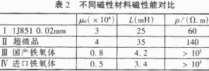
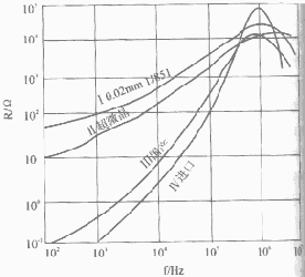
The higher the better, the electrical characteristics of the magnetic material in the circuit should also be considered. In order to illustrate, different types of soft magnetic materials with high μ0 are selected below to measure their frequency and impedance curves under the same conditions, reflecting the insertion loss trend of the inductor core, and their performance is shown in Table 2 and Figure 3.
Curve IV is a foreign inductive core (Mn-Zn ferrite) specially used for anti-common-mode interference, compared with domestic ferrite, 100Hz ~ in the low frequency band 10000Hz, due to the high resistivity of the material itself, the AC equivalent resistance is small, indicating that the loss of interference signal in this frequency band is very small, and the current mainly plays a major role in inductive reactance, it can be seen that ferrite materials have no inhibition effect on low-frequency interference signals, and ultracrystalline and 1J851 materials due to the relatively low resistivity of the material, with the increase of frequency loss also increases, It can be seen that the equivalent resistance R caused by eddy current losses of the core is much larger than that of ferrite. In the frequency band R of 10kHz~100kHz continues to increase, the suppression of interference signals in this frequency band is also increasing, of which 1J851 and ultracrystalline materials have the greatest attenuation to the suppression of interference signals, while ferrites are small. For linear filters, the power supply with operating frequency of 50Hz~60Hz or 400Hz~800Hz should be eliminated or attenuated less frequently For 10kHz interference signals, it is best to use metallic magnetic materials (or amorphous ultracrystalline). The absorption of interference signals by ferrites in this frequency band is obviously not as good as that of metallic magnetic materials. When around the frequency band 100kHz~1MHz, the ferrite material R increases sharply, while the metal magnetic material and ultracrystalline still rise steadily, and the imported ferrite reaches a peak at 1MHz. R is the largest, followed by 1J851. Domestic ferrite ranks third ultracrystalline, and its peak is around 3MHz, but the change is relatively flat. From the curve change, it can be seen that although the peak absorption of ferrite is around 7MHz, the absorption region is relatively narrow, while the absorption zone of metal magnetic materials is relatively wide, so the absorption sensitivity of different materials to different frequencies is different. Therefore, it is very important that the inductor material selected when manufacturing the common-mode filter must be selected according to the suppression frequency band range required by the circuit. At the same time, the comparison of the curve from Table 1 and Figure 2 shows that the higher the inductance, the better, but its electrical parameters should be considered, and the inductance cannot be increased by increasing the number of coil turns. This increases the high-frequency parasitic capacitance.
(2 The choice of differential mode filter inductor material is completely different from that of common-mode filter inductor, because the inductor and the load are connected in series, the input current or output current directly passes through the inductor core, and its AC (DC) current is large, of course, high permeability materials cannot be used. In order to adapt to the needs of the inductive core of the differential mode anti-interference filter, the method of increasing the demagnetization magnetic field with air gap between ferrite or metal magnetic materials is initially used to reduce the permeability and increase the anti-saturation capacity of the core. However, this is obviously inappropriate for the anti-interference filtering of alternating currents used at the power input.
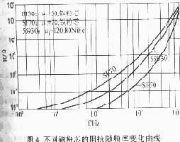
Not only is there a strong alternating leakage magnetic field at the open air gap caused by great radiation interference, but also local loss at the air gap fracture and heating, resulting in the deterioration or even disappearance of ferrite magnetism. Because the ferrite Curie temperature is 200 °C, it is around μ0 at this temperature It is reduced to zero, at which point the filtering effect has been lost. In addition, due to magnetostriction, new mechanical noise is generated at the air gap, which pollutes the environment. For this reason, people use novel composite magnetic powder cores. This is currently the most ideal filter inductor material, it is the metal soft magnetic powder by insulation wrapping pressing annealing, it is equivalent to a concentrated air gap dispersed into tiny holes evenly distributed in the core, not only the material saturation strength increased, but also the resistivity of the core than the original increased orders of magnitude and isotropic, changed the disadvantages of metal magnetic materials can not be used at high frequencies. This is why all differential mode filter inductors in foreign countries use magnetic powder cores instead of open ferrite cores. Frequency-impedance curves are measured by magnetic powder cores with various properties (see Figure 4). The change curve in the figure shows inductors with different magnetic properties, and their impedance and frequency change are not the same. The impedance of iron powder core SF70 and 55930 is basically unchanged when the interference frequency is < 2kHz, indicating no absorption, while SF30 is less than 60kHz There is also no absorption effect on the signal. Absorption increases rapidly around 2MHz, with strongest absorption near 10MHz, while SF70 is at 100kHz Not much will change later. It can be seen that the absorption frequency band of interference signals is also different for materials with different properties. Most of the electronic dimming equipment widely used at home and abroad adopts phase-shifted thyristor dimming. At the moment of thyristor conduction, electromagnetic interference caused by a large number of high-frequency harmonics will be generated due to sudden current changes, which not only seriously affects audio equipment, lamps, video recording and other equipment, but also seriously interferes with the power grid system. Anti-interference inductors must be installed (LeeColorTran in the United States, Lank in the United Kingdom, and RDS in Japan use this method to suppress interference). For convenience, the analysis current rise time tr is used to determine the degree of immunity of the inductor core. The data for different materials are shown in Table 3.
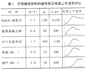
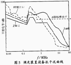
The effect of suppressing interference in the industrial detection of dimming lamps can be expressed by the current rise time tr when the electronic dimmer is turned on. The longer the rise time, the smaller the higher harmonic component of the circuit and the better the suppression effect. It is not difficult to see from the table that the domestic ZW-1 inductor tr time can be as high as 450μs, while the magnetic permeability is only 70. Although the open amorphous strip core has the highest permeability (μe=800), the current rise time is too short and only 100μs, and there is serious mechanical noise. This shows that the anti-interference ability after adding inductance is not good with high magnetic permeability, nor is it good with low magnetic permeability, but is related to the selected magnetic material material. For further analysis, the interference voltage of different materials is measured under the same conditions, Figure 5 is the British Lank, domestic ZW-1 The power supply terminal of the magnetic powder core and the normally open core interferes with the voltage and frequency curve.
According to the measurement results of "Allowable value and measurement method of radio interference of electronic dimming equipment", it is not difficult to see the domestic ZW-1 inductor and the British Lank Compared with inductors, the anti-interference level of domestic ZW-1 inductors is below the A standard, while the British Lank inductors are in The 0.16MHz~3.5MHz frequency band exceeds the standard, and the anti-interference inductor made of open silicon steel sheet is in the frequency band 0.01MHz-1.2MHz are over the mark. It is impossible to meet the standard with an open core as an anti-interference inductor. At present, most of the domestic dimming lamps use ferrite magnetic rings as anti-interference inductors, which is obviously wrong. Instead of suppressing interference, it increases it, because ferrites always operate in the saturation zone.
Figure 6 shows the attenuation curve of a 100A anti-interference filter for a program-controlled switch. Anti-interference attenuation curve I is an imported similar filter, and the attenuation of interference level in the range of 0.01MHz~100MHz is relatively uniform and smooth. Curve II uses open ferrite as a filter, and the peak value when the frequency is 0.4MHz~0.8MHz indicates that the attenuation of the interference signal in this frequency band is small and does not meet the requirements. Later, it was replaced by the iron powder core of Micrometals Company of the United States, and the anti-interference ability in the 0.2MHz~0.45MHz band was weak (such as curve III But better than open ferrite, it's still not ideal. Because the most nerve-wracking thing for the communication power supply is low-frequency interference. Later, the interference level of the filter made of specially developed magnetic powder core, such as curve IV, was better than curve II and III, and even better than the performance of similar foreign filters. From the above examples, it can be seen that special attention should be paid to the selection of filter inductors when developing EMI filters. Not only the appropriate magnetic material should be selected, but also the magnetic properties suitable for the required attenuation band. Therefore, the selection of magnetic materials plays a pivotal role in EMI filters.
4 The development trend of anti-interference filters
Current electronic circuits are shifting to high-speed digital circuits. High assembly density and high computing speed place higher demands on EMC. The miniaturization, multi-function and mobile development of electronic products has promoted the transfer of electronic products to surface mount technology in assembly methods, and further reduced interference. At the same time, in order to improve its dynamic response and reduce interference, it is necessary to reduce the lead inductance of the power supply bus. The most effective method is to install the power supply directly near the load, and use a decentralized power supply method (that is, a small power source) instead of a centralized power supply form (a high-power source), which greatly reduces the length of the lead and effectively reduces the radiation interference. Therefore, in the next few years, the United States will vigorously develop low-power 16W~25W low-voltage (output voltage minimum 1.2V) DC/DC Switching power supply. It can be seen that chip magnetic devices are one of the key materials for miniaturization, which can be divided into wirewound chip inductors, laminated chip inductors, and thin film chip inductors. To this end, Shanghai Iron and Steel Research Institute has begun to develop metal film inductors and thin film transformer components. At present, some important research institutes in the United States and Japan have begun to study thin-film inductors and thin-film transformers, and combine them with integrated components to form novel ultra-small, high-reliability, high-immunity power modules. It can be seen that ultra-small inductors and transformers will be the development direction of magnetic components in the 21st century
NEWS
Wettbewerb erfolgreich beendet
2023-05-18
Kontakt
Tel : +86-20-37720102
Cell : +86-13392672318
Email : info@jchncores.com
WhatsApp : +86-15986765253
Adresse: No.18, Suida St. Huangpu District, Guangzhou
Website : www.jchncores.com
Copyright 2023 JCHN Cores
